

The following are some common maintenance procedures for the Polaris 120 INDY youth snowmobile. Always make sure the engine is stopped before attempting adjustments. Stop the engine, raise the hood, make the adjustment, secure shields and guards, secure the hood and then re-start the engine to check its operation. The same is true of track alignment.
For an overview of the 120 INDY, click here.
Oil Change
When checking the oil, make sure to maintain the oil level between the upper and lower marks on the dipstick.
To check the oil:
1. Position the vehicle on a level surface.
2. Stop the engine.
3. Remove the dipstick (1) and wipe it dry with a clean shop towel.
4. Insert the dipstick into the oil fill hole completely, but do not thread it.
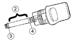
5. Remove the dipstick and view the oil level (2).
6. If the oil level is below the upper mark (3) on the dipstick, add the recommended oil to the upper mark (4).
To change the oil:
1. Support the rear of the snowmobile slightly off the ground with an appropriate snowmobile support.
2. Place a drain pan under the drain plug (1). Tip: The drain plug is located under the bulkhead and in front of the engine.

3. Remove the drain plug.
4. Remove the dipstick (2) and wipe it dry with a clean shop towel. Tip: The oil will drain faster with the dipstick removed.
5. Allow the oil to drain completely.
6. Reinstall the drain plug and sealing washer. Torque to 10 ft-lbs (13.5 Nm).
7. Using a long funnel, pour 20 ounces (0.6 liters) of the recommended oil into the oil fill hole. Tip: Polaris recommends using Performance Synthetic 4-Stroke oil (PS-4 or PS-4 Plus) for the 120 INDY.
8. Insert the dipstick into the oil fill hole completely, but do not thread it.
9. Remove the dipstick and view the oil level.
10. If the oil level is below the lower mark on the dipstick, add the recommended oil to the upper mark.
Throttle and Brake
The throttle and brake are the primary controls of the snowmobile. If either should malfunction, the operator could lose control, which could lead to serious injury or death. Always check the throttle and brake levers for proper operation before the vehicle is driven.
When checking the throttle, make sure the throttle lever compresses evenly and smoothly. When the lever is released, it should immediately return to the idle position without binding or hesitation. If the throttle does not function smoothly, do not start the engine. Have the throttle serviced before operating the snowmobile.
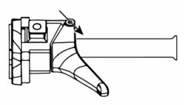
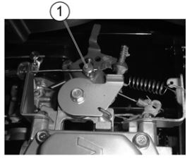
Test the throttle safety switch on a daily basis before the vehicle is used. With the engine idling, hold the throttle lever pin stationary by exerting pressure on the pivot pin in the direction shown in the illustration. Apply a slight amount of throttle opening. A properly functioning switch must shut down the engine.
The throttle safety switch is designed to stop the engine whenever all pressure is removed from the throttle lever and the throttle cable or valve does not return to the normal closed position.
If excessive play develops in the throttle cable, the safety switch may be activated and will prevent the engine from starting. If the engine doesn’t start and throttle safety switch malfunction is suspected, you can bring the machine to your authorized Polaris Dealer for service.
Lubricate the throttle cable occasionally. Always do this with the engine off. Turn the handlebars to the left and lubricate liberally with Polaris All Season Grease.
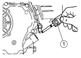
Lubricate the throttle cable pivot slug (1) every 50 hours or twice a year using an aerosol lubricant.
Squeeze the brake lever toward the handlebar. When the lever is released, it should return to its original position smoothly. If the lever hesitates or seems sticky, do not start the engine. Have the brakes serviced before operating the snowmobile.
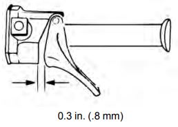
Depress the brake lever fully. Measure the clearance between the lever and the brake block. Clearance should be no more than 3/4-inch (1.9 cm). Excessive travel indicates a need to adjust the brake cable.

If proper brake cable adjustment cannot be achieved using the following methods, check the brake band. If the brake band has excessive wear, your Polaris Dealer can assist with the installation of a new band.
Warning: Improper brake adjustment can result in a brake failure, which could result in severe injury or death. Perform the adjustment procedures exactly as outlined, or your Polaris Dealer can provide assistance.
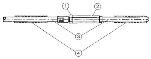
1. Slide the two rubber protector covers (4) back to expose the cable adjuster.
2. Using an 8mm wrench to hold the barrel nut (2), loosen the jam nut (1) with a 10mm wrench.
3. With your left hand, grasp the cables (3) as close to the adjuster as possible. Use your right hand to rotate the barrel nut until you have reached the proper brake level adjustment.
4. Check the actuator linkage to ensure there is adequate freedom of movement for positive brake operation and that all floating parts move freely and that all parts are mounted securely. Tighten the hardware as required.
5. Tighten the adjuster nut and slide the rubber protectors onto the adjuster.
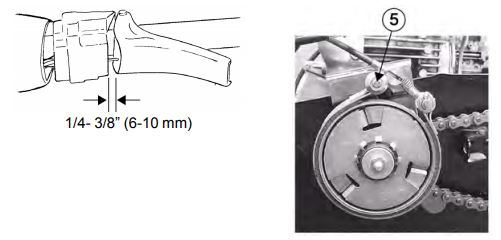
6. The brake band is adjusted correctly when brake lever freeplay is 1/4 to 3/8 inch (6 to 10 mm) and clearance between the brake lever and block with the lever fully depressed is no more than 3/4 inch (19 mm). Torque the band bolt nut (5) to 6 ft-lbs (8 Nm).
Track Tension
Track adjustment is critical for proper handling. Always maintain correct tension and alignment.

To check the track tension:
1. Operate the snowmobile to warm up the track.
2. Stop the engine.
3. Support the rear of the snowmobile slightly off the ground with an appropriate snowmobile support.
4. Hang a 10-pound (4.5 kg) weight (1) 8 inches (20 cm) (2) from the center of the rear idler wheel (4).
5. Measure the distance between wear surface of the track clip and the plastic slider at the point where the weight is hanging. Deflection at this point should be 3/4 inch (19 mm).
6. If the track tension needs adjustment (3), follow the procedure outlined below. If the rear idler wheel assembly washers (5) are removed, be sure they are reinstalled with the domed side of the washer facing outward as shown (6).
To adjust the track tension:
1. Loosen the rear idler shaft bolt.
2. Tighten or loosen the track adjusting screws to provide equal adjustment on both sides of the track.
3. Repeat the measurement on the other side of the track. Tip: Check tension more frequently when the machine is new. Warning: When performing these checks and adjustments, stay clear of all moving parts to avoid serious personal injury. Make sure the track contains no objects that could be thrown out while the track is rotating. Keep clear of the track. This includes but is not limited to hands, tools, feet and clothing. Make sure no one is standing close to the machine while the track is rotating.
4. Start the engine and slowly rotate the track at least five revolutions. Allow the track to stop rotating by itself (do not apply brakes).
5. Check and adjust the track alignment as outlined below.
6. Tighten the idler shaft bolt. Torque to 35 to 40 ft-lbs (47 to 54 Nm).
7. Re-adjust the toe block to proper spacing and tighten.
Track Alignment
Check the track alignment at the intervals outlined in the periodic maintenance chart in your Owner’s Manual. Make sure the track is centered and running evenly on the slide rails. Misalignment will cause excessive wear to the track and slide rail. Warning: When performing these checks and adjustments, stay clear of all moving parts to avoid serious personal injury. Make sure the track contains no objects that could be thrown out while the track is rotating. Keep clear of the track. This includes but is not limited to hands, tools, feet and clothing. Make sure no one is standing close to the machine while the track is rotating.
1. Support the rear of the snowmobile slightly off the ground with an appropriate snowmobile support.
2. Start the engine and apply a small amount of throttle until the track turns slowly at least five complete revolutions. Stop the engine.
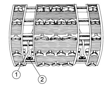
3. Inspect the track alignment by looking through the track windows to make sure the rails (1) are evenly spaced on each side. If the track runs to the left, loosen the left idler wheel mounting bolt and tighten the left track adjusting bolt. If the track runs to the right, loosen the right idler wheel mounting bolt and tighten the right track adjusting bolt.
4. After adjustments are complete, tighten the locknuts and idler shaft bolts. Torque to 35 to 40 ft-lbs (47 to 54 Nm).
5. Repeat step 2 to verify proper alignment.
Spark Plugs
A new engine can cause temporary spark plug fouling due to the preservative added during the assembly process. Avoid prolonged idle speeds, which cause plug fouling and carbonization.
Refer to the specifications section of your Owner’s Manual for recommended spark plug type and gap. Using non-recommended spark plugs can result in serious engine damage. Always use the spark plugs recommended for your snowmobile.
Spark plug condition is indicative of engine operation. The spark plug firing end condition should be read after the engine has been warmed up and the vehicle has been driven. Immediately check the spark plug for the correct color.
A normal insulator tip is gray, tan or light brown. There will be a few combustion deposits. The electrodes are not burned or eroded. This indicates the proper type and heat range for the engine and the service.
The tip should not be white. A white insulator tip indicates overheating, caused by use of an improper spark plug or incorrect carburetion adjustments.
A wet fouled insulator tip is black. A damp oil film covers the firing end. There may be a carbon layer over the entire nose. Generally, the electrodes are not worn. General causes of fouling are excessive oil, use of non-recommended oil, improper use of the choke or incorrect carburetion adjustments. Warning: A hot exhaust system and engine can cause serious burns. Wear protective gloves when removing a spark plug for inspection.
To remove and replace a spark plug:
1. Stop the engine.
2. Remove the spark plug cap.
3. Using the special wrench provided in the tool pouch, rotate the spark plug counterclockwise to remove it.
4. Reverse the procedure for spark plug installation.
Torque to 12 to 14 ft-lbs (16 to 19 Nm).
Ski Skags
The skag (1) is a replaceable bar attached to the underside of the ski. The purpose of the skag is to assist in turning the snowmobile and to prevent the wearing away of the ski caused by contact with roads and other bare terrain.
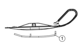
Check skags weekly to maintain positive steering characteristics. Replace skags when they are worn to half their original diameter. Tip: See your dealer’s track studding and skag chart for the recommended skags. Warning: Worn skis and/or skags will adversely affect handling and can cause loss of vehicle control, which can lead to serious injury or death. Replace worn skis and/or skags when inspection reveals wear.
To replace a skag:
1. Raise and support the front of the snowmobile so the skis are approximately 6 inches (15 cm) off the ground.
2. Remove the attaching nuts and pry the skag downward.
3. Remove the forward portion of the skag.
4. Reverse this procedure for new skag installation.
Slider Replacement
Polaris rail slides have a wear limit indicator groove to indicate the minimum permissible slide thickness (1). Replace the rail slides if they are worn to the top of the groove (2) at any point along their length. Failure to do so may result in permanent damage to the track or rails.

For more information, see your authorized Polaris Dealer. To find a dealer near you, use the Dealer Locator.
Maintenance tips, procedures and specifications can be found in your Owner's Manual.
To find diagrams and replacement part numbers, use the online parts catalog.
Unless noted, trademarks are the property of Polaris Industries Inc.
© 2022 Polaris Industries Inc.


